Application
The ST series spring-type DIN rail terminal blocks are designed for reliable conductor connection and potential distribution in low-voltage electrical systems.
They are widely used in control cabinets, switchgear assemblies, power distribution panels, and industrial automation equipment, providing fast, secure, and vibration-resistant wiring for solid and stranded conductors.
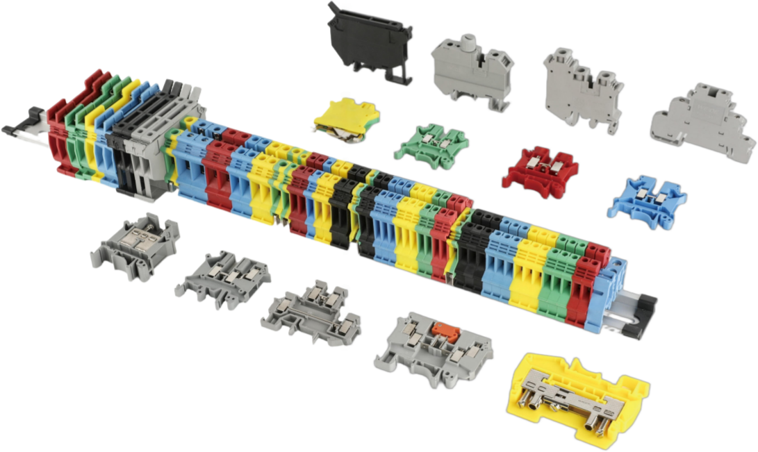
Key Specifications
| Key Specifications | ST1.5 | ST-1.5TWIN | ST-1.5TWIN-PE | ST-1.5QUKTTRO | ST-1.5QUKTTRO-PE | STTB-1.5 | STTB-1.5-PE | ST-1.5PE | ST2.5 | ST2.5-PE | STTB2.5 | STTB2.5-PE | ST2.5-TWIN | ST2.5-TWIN-PE | ST2.5-QUATTRO | STTB-2.5 | ST2.5-QUATTRO-PE | ST2.5-3L | ST4 | ST4-PE | ST4-TWIN | ST4-TWIN-PE | ST4-QUATTRO | ST4-QUATRRO-PE | STTB-4 | STTB-4PE | ST-6 | ST6-PE | ST-10 | ST-10-PE | ST-16 | ST-16PE | ST-6S | ST4-HESI | | Electrical Specifications | | | | | | Rated Insulation Voltage(V) | 500 | 500 | 500 | 500 | 500 | 500 | 500 | 500 | 800 | 800 | 500 | 500 | 800 | 800 | 800 | 500 | 800 | 500 | 800 | 800 | 800 | 800 | 800 | 800 | 500 | 500 | 800 | 800 | 800 | 800 | 800 | 800 | 800 | 500 | | Rated Current(A) | 17.5 | 17.5 | 17.5 | 17.5 | 17.5 | 17.5 | 17.5 | 17.5 | 24 | 24 | 24 | 24 | 24 | 24 | 24 | 24 | 24 | 24 | 32 | 32 | 32 | 32 | 32 | 32 | 32 | 32 | 41 | 41 | 57 | 57 | 76 | 76 | 20 | 6.3 | | Standard | IEC 60947-7-1 | IEC 60947-7-1 | IEC 60947-7-1 | IEC 60947-7-1 | IEC 60947-7-1 | IEC 60947-7-1 | IEC 60947-7-1 | IEC 60947-7-1 | IEC 60947-7-1 | IEC 60947-7-1 | IEC 60947-7-1 | IEC 60947-7-1 | IEC 60947-7-1 | IEC 60947-7-1 | IEC 60947-7-1 | IEC 60947-7-1 | IEC 60947-7-1 | IEC 60947-7-1 | IEC 60947-7-1 | IEC 60947-7-1 | IEC 60947-7-1 | IEC 60947-7-1 | IEC 60947-7-1 | IEC 60947-7-1 | IEC 60947-7-1 | IEC 60947-7-1 | IEC 60947-7-1 | IEC 60947-7-1 | IEC 60947-7-1 | IEC 60947-7-1 | IEC 60947-7-1 | IEC 60947-7-1 | IEC 60947-7-1 | IEC 60947-7-1 | | Conductor & Connection Specifications | | | | | | Solid Conductor Range(mm²) | 0.14-1.5 | 0.14-1.5 | 0.14-1.5 | 0.14-1.5 | 0.14-1.5 | 0.14-1.5 | 0.14-1.5 | 0.14-1.5 | 0.2-4 | 0.2-4 | 0.2-4 | 0.2-4 | 0.2-4 | 0.2-4 | 0.2-4 | 0.2-4 | 0.2-4 | 0.2-4 | 0.2-6 | 0.2-6 | 0.2-6 | 0.2-6 | 0.2-6 | 0.2-6 | 0.2-6 | 0.2-6 | 0.5-10 | 0.5-10 | 1.5-16 | 1.5-16 | 1.5-25 | 1.5-25 | 0.2-6 | 0.2-4 | | Stranded Conductor Range(mm²) | 0.14-1.5 | 0.14-1.5 | 0.14-1.5 | 0.14-1.5 | 0.14-1.5 | 0.14-1.5 | 0.14-1.5 | 0.14-1.5 | 0.2-2.5 | 0.2-2.5 | 0.2-2.5 | 0.2-2.5 | 0.2-2.5 | 0.2-2.5 | 0.2-2.5 | 0.2-2.5 | 0.2-2.5 | 0.2-2.5 | 0.2-4 | 0.2-4 | 0.2-4 | 0.2-4 | 0.2-4 | 0.2-4 | 0.2-4 | 0.2-4 | 0.5-6 | 0.5-6 | 1.5-10 | 1.5-10 | 1.5-16 | 1.5-16 | 0.2-6 | 0.2-4 | | Conductor Entry Direction | Top entry | Top entry | Top entry | Top entry | Top entry | Top entry | Top entry | Top entry | Top entry | Top entry | Top entry | Top entry | Top entry | Top entry | Top entry | Top entry | Top entry | Top entry | Top entry | Top entry | Top entry | Top entry | Top entry | Top entry | Top entry | Top entry | Top entry | Top entry | Top entry | Top entry | Top entry | Top entry | Top entry | Top entry | | Material & Environmental Specifications | | | | | | Insulation Material | PA66 | PA66 | PA66 | PA66 | PA66 | PA66 | PA66 | PA66 | PA66 | PA66 | PA66 | PA66 | PA66 | PA66 | PA66 | PA66 | PA66 | PA66 | PA66 | PA66 | PA66 | PA66 | PA66 | PA66 | PA66 | PA66 | PA66 | PA66 | PA66 | PA66 | PA66 | PA66 | PA66 | PA66 | | Pollution Degree | 3 | 3 | 3 | 3 | 3 | 3 | 3 | 3 | 3 | 3 | 3 | 3 | 3 | 3 | 3 | 3 | 3 | 3 | 3 | 3 | 3 | 3 | 3 | 3 | 3 | 3 | 3 | 3 | 3 | 3 | 3 | 3 | 3 | 3 | | Color | customize | customize | Yellow-Green | customize | Yellow-Green | customize | Yellow-Green | Yellow-Green | customize | Yellow-Green | customize | Yellow-Green | customize | Yellow-Green | customize | customize | Yellow-Green | customize | customize | Yellow-Green | customize | Yellow-Green | customize | Yellow-Green | customize | Yellow-Green | customize | Yellow-Green | customize | Yellow-Green | customize | Yellow-Green | customize | customize | | Installation and Operation | | | | | | Thickness(mm) | 4.2 | 4.2 | 4.2 | 4.2 | 4.2 | 4.2 | 4.2 | 4.2 | 5.2 | 5.2 | 5.2 | 5.2 | 5.2 | 5.2 | 5.2 | 5.2 | 5.2 | 5.2 | 6.2 | 6.2 | 6.2 | 6.2 | 6.2 | 6.2 | 6.2 | 6.2 | 8.2 | 8.2 | 10.2 | 10.2 | 12.2 | 12.2 | 8.2 | 6.2 | | Width(mm) | 49.5 | 60.5 | 60.5 | 73.5 | 73.5 | 46.5 | 46.5 | 49.5 | 49.5 | 49.5 | 68.5 | 68.5 | 60.5 | 60.5 | 73.5 | 68.5 | 73.5 | 101 | 56.5 | 56.5 | 72.5 | 72.5 | 88 | 88 | 84.5 | 84.5 | 69.5 | 69.5 | 71.5 | 71.5 | 80.5 | 80.5 | 84 | 62 | | Height | 36.5 | 36.5 | 36.5 | 36.5 | 36.5 | 36.5 | 36.5 | 36.5 | 36.5 | 36.5 | 46.5 | 46.5 | 36.5 | 36.5 | 36.5 | 46.5 | 36.5 | 57 | 36.5 | 36.5 | 36.5 | 36.5 | 36.5 | 36.5 | 47.5 | 47.5 | 43.5 | 43.5 | 50.5 | 50.5 | 51 | 51 | 42.5 | 64 | | Auxiliary tool (screwdriver) | SZF 0-0.4*2.5 | SZF 0-0.4*2.5 | SZF 0-0.4*2.5 | SZF 0-0.4*2.5 | SZF 0-0.4*2.5 | SZF 0-0.4*2.5 | SZF 0-0.4*2.5 | SZF 0-0.4*2.5 | SZF 0-0.6*3.5 | SZF 0-0.6*3.5 | SZF 0-0.6*3.5 | SZF 0-0.6*3.5 | SZF 0-0.6*3.5 | SZF 0-0.6*3.5 | SZF 0-0.6*3.5 | SZF 0-0.6*3.5 | SZF 0-0.6*3.5 | SZF 0-0.6*3.5 | SZF 1-0.6*3.5 | SZF 1-0.6*3.5 | SZF 1-0.6*3.5 | SZF 1-0.6*3.5 | SZF 1-0.6*3.5 | SZF 1-0.6*3.5 | SZF 1-0.6*3.5 | SZF 1-0.6*3.5 | SZF 2-0.8*4.0 | SZF 2-0.8*4.0 | SZF 3-1.0*5.5 | SZF 3-1.0*5.5 | SZF 3-1.0*5.5 | SZF 3-1.0*5.5 | SZF 2-0.8*4.0 | SZF 2-0.8*4.0 | | Accessories | | | | | | End Cover | D-ST-2.5 | D-ST-2.5TWIN | D-ST-2.5TWIN | D-ST-2.5QUATTRO | D-ST-2.5QUATTRO | D-STTB-1.5 | D-STTB-1.5 | D-ST-2.5 | D-ST-2.5 | D-ST-2.5 | D-STTB2.5 | D-STTB2.5 | D-ST-2.5TWIN | D-ST2.5-TWIN | D-ST-2.5QUATTRO | D-STTB-2.5 | D-ST2.5-QUATTRO | D-ST2.5-3L | D-ST-4 | D-ST-4 | D-ST4-TWIN | D-ST4-TWIN | D-ST4-QUATTRO | D-ST4-QUATTRO-PE | D-STTB-4 | D-STTB-4 | D-ST-6 | D-ST-6 | D-ST-10 | D-ST-10 | D-ST-16 | D-ST-16 | D-ST-6S | – | | End Clamp | E/3 | E/3 | E/3 | E/3 | E/3 | E/3 | E/3 | E/3 | E/3 | E/3 | E/3 | E/3 | E/3 | E/3 | E/3 | E/3 | E/3 | E/3 | E/3 | E/3 | E/3 | E/3 | E/3 | E/3 | E/3 | E/3 | E/3 | E/3 | E/3 | E/3 | E/3 | E/3 | E/3 | E/3 | | Insertion Bridge | FBS2-4 /3-4/4-4/5-4/10-4/20-4 | FBS2-4 /3-4/4-4/5-4/10-4/20-4 | – | FBS2-4 /3-4/4-4/5-4/10-4/20-4 | – | FBS2-4 /3-4/4-4/5-4/10-4/20-4 | – | – | FBS2-5 /3-5/4-5/5-5/10-5/20-5 | – | FBS2-5 /3-5/4-5/5-5/10-5/20-5 | – | FBS2-5 /3-5/4-5/5-5/10-5/20-5 | – | FBS2-5 /3-5/4-5/5-5/10-5/20-5 | FBS2-5 /3-5/4-5/5-5/10-5/20-5 | – | FBS2-5 /3-5/4-5/5-5/10-5/20-5 | FBS2-6 /3-6/4-6/5-6/10-6/20-6 | – | FBS2-6 /3-6/4-6/5-6/10-6/20-6 | – | FBS2-6 /3-6/4-6/5-6/10-6/20-6 | – | FBS2-6 /3-6/4-6/5-6/10-6/20-6 | – | FBS2-8 /3-8/4-8/5-8/10-8/20-8 | – | FBS2-10 | – | FBS2-12 | – | – | FBS2-6 /3-6/4-6/5-6/10-6/20-6 | | Marker Strip | ZB4/ZBF4 | ZB4/ZBF4 | ZB4/ZBF4 | ZB4/ZBF4 | ZB4/ZBF4 | ZBF4 | ZBF4 | ZB4/ZBF4 | ZB5/ZBF5 | ZB5/ZBF5 | ZB5/ZBF5 | ZB5/ZBF5 | ZB5/ZBF5 | ZB5/ZBF5 | ZB5/ZBF5 | ZBF5 | ZB5/ZBF5 | ZBF5 | ZB6/ZBF6 | ZB6/ZBF6 | ZB6/ZBF6 | ZB6/ZBF6 | ZB6/ZBF6 | ZB6/ZBF6 | ZBF6 | ZB6/ZBF6 | ZB8/ZBF8 | ZB8/ZBF8 | ZB10/ZBF10 | ZB10/ZBF10 | ZB12/ZBF12 | ZB12/ZBF12 | ZBF8 | ZB6/ZBF6 | | Partition Plate | ATP-ST/PT | ATP-ST/PT | – | ATP-ST/PT | – | ATP-ST/PT | – | – | ATP-ST/PT | – | ATP-ST/PT | – | ATP-ST/PT | – | ATP-ST/PT | ATP-ST/PT | – | ATP-ST/PT | ATP-ST/PT | – | ATP-ST/PT | – | ATP-ST/PT | – | ATP-ST/PT | – | ATP-ST/PT | – | – | – | – | – | ATP-ST/PT | – | | – | | | | | | Order Number | | | | | | | | | | | | | | | | | | | | | | | | | | | | | | | | | | |
|
Installation and Operation
- Mount the terminal block onto the standard TH35 DIN rail.
- Use an appropriate tool to actuate the spring mechanism.
- Insert the conductor fully into the clamping point.
- Release the spring to secure the conductor.
- Ensure all conductors are properly connected before energizing.
Installation Notes
- Ensure conductors comply with the specified conductor ranges.
- Use appropriate tools to operate the spring mechanism.
- Installation and maintenance must be carried out with power disconnected.