

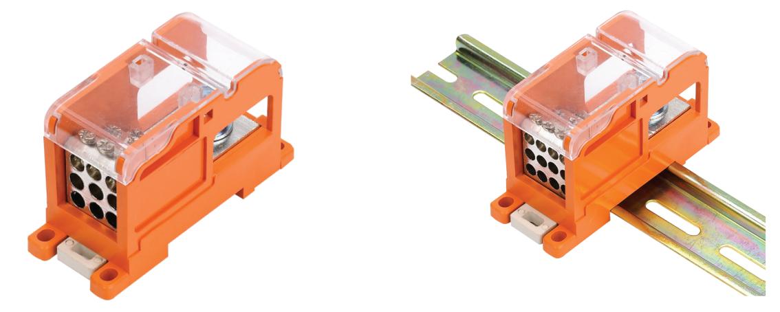
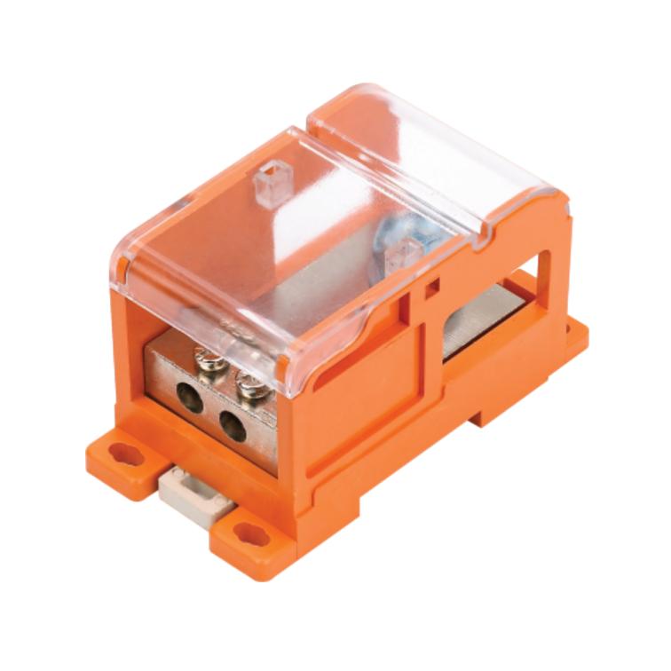
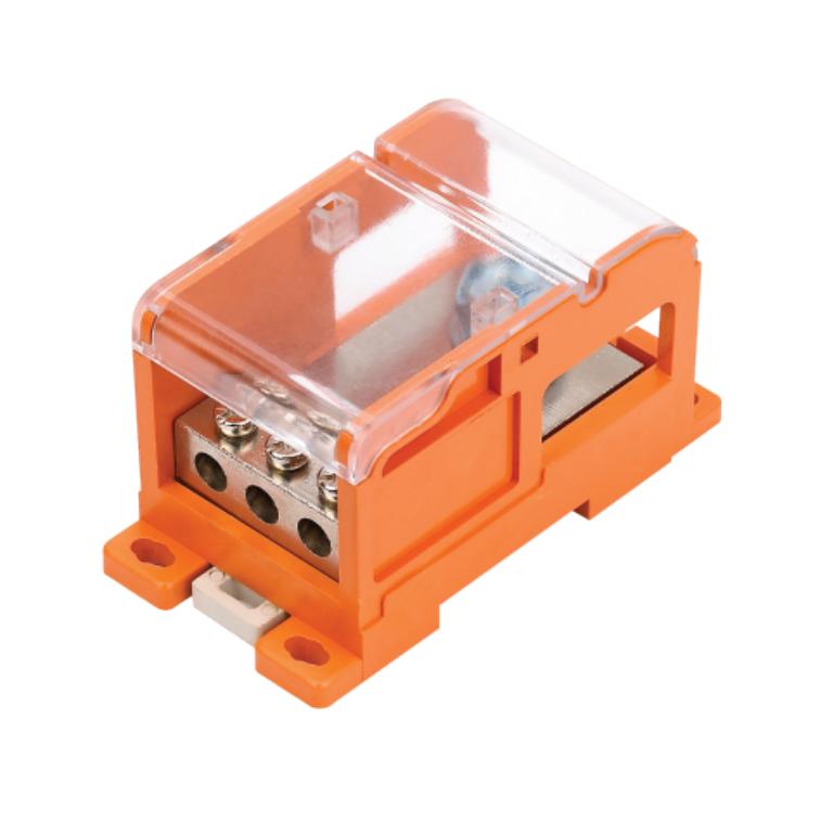
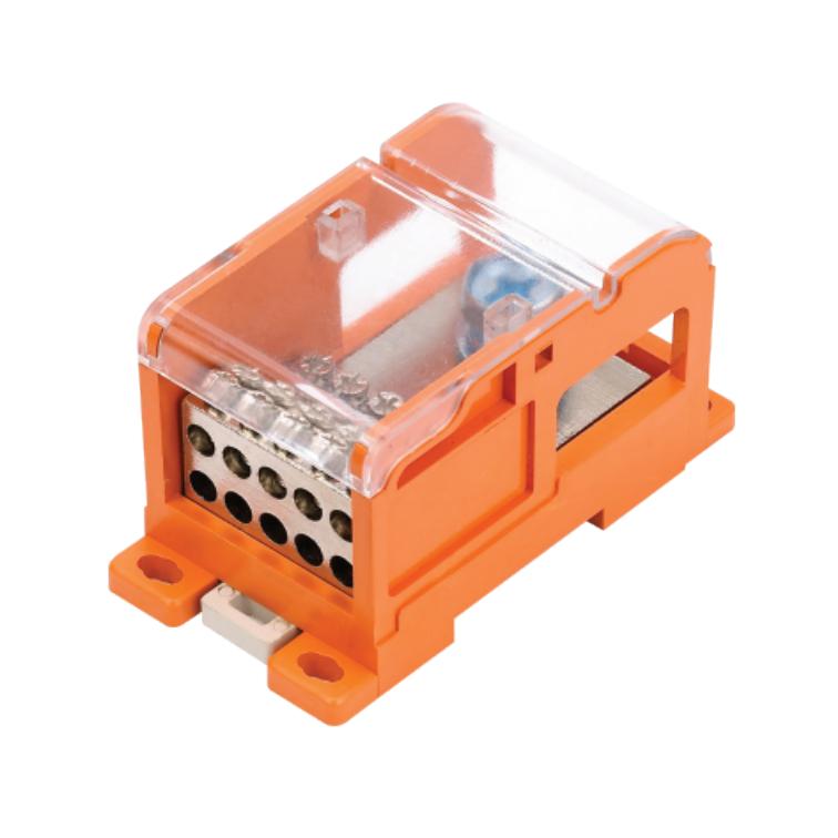
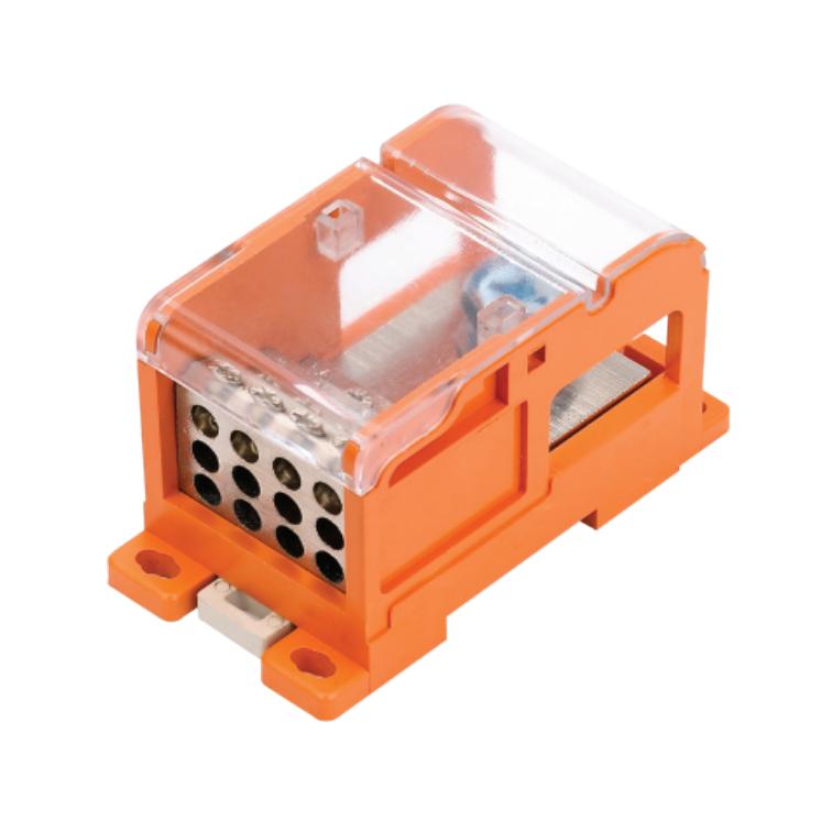
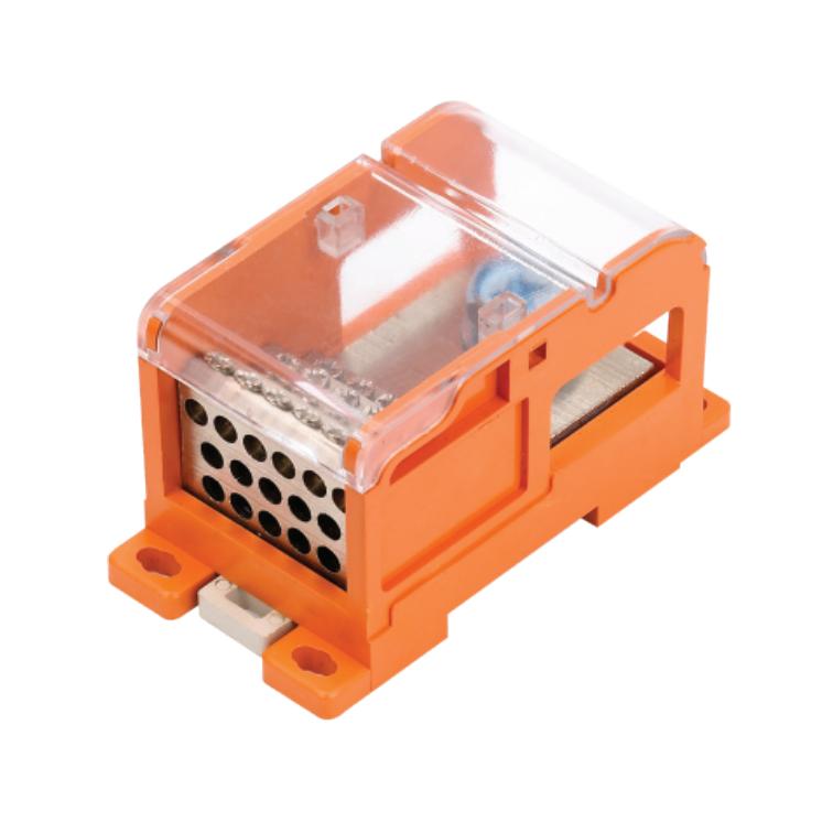
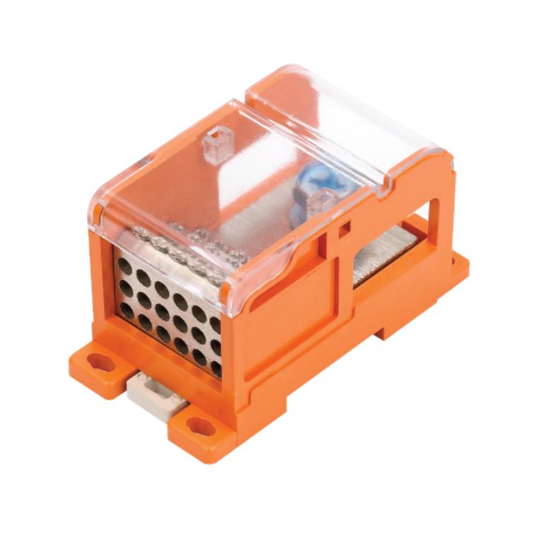
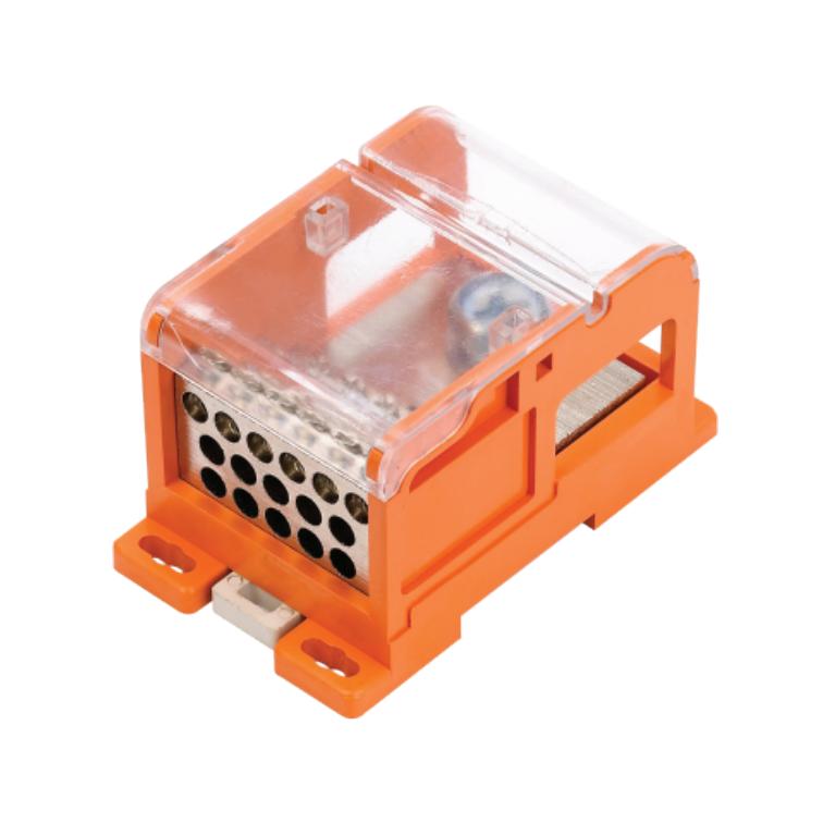
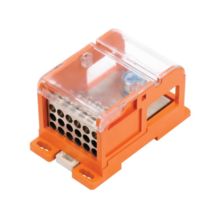
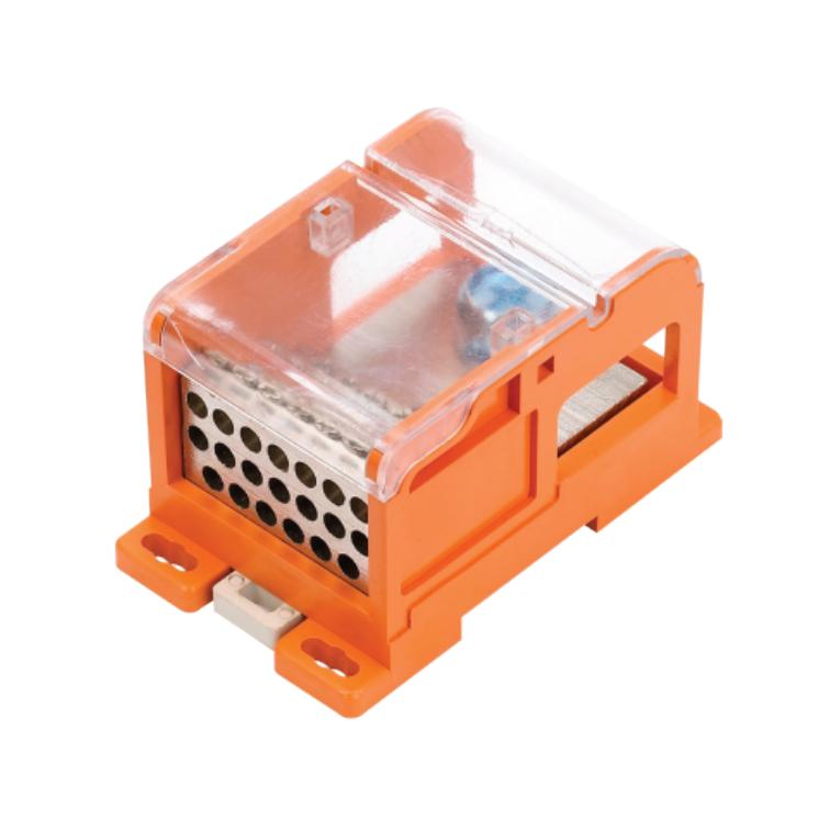
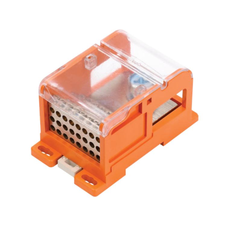
FJ6/JTS3-240B Series Power Distribution Terminal Block(Cable Lug/Busbar Line-in)
Product Features
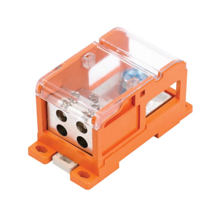
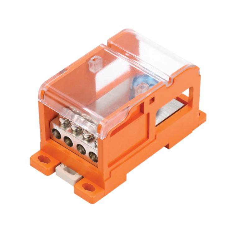
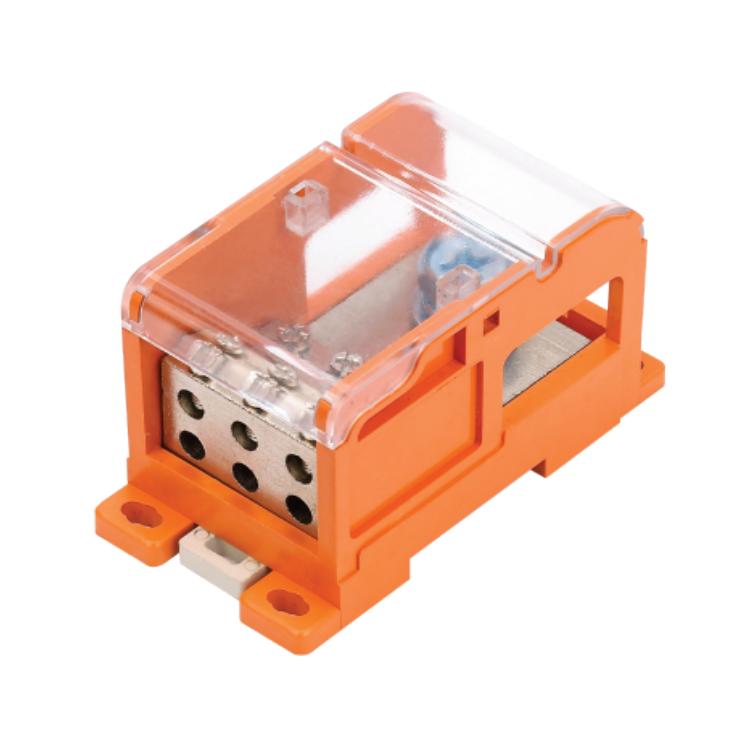
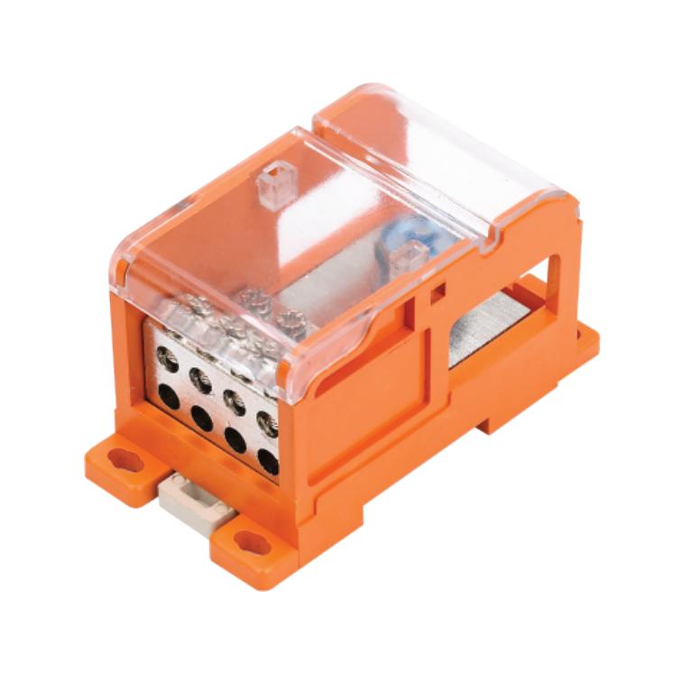
- Power distribution terminal block with one input and multiple outputs for multi-circuit power and circuit distribution.
- Supports multiple line-in connection methods:
– Cable lug connection.
– Copper busbar connection.
- Supports line-in connection from three directions, allowing flexible wiring layouts.
- Protective cover fits securely and remains firmly in place after installation, preventing accidental loosening.
- High current-carrying capability for main power infeed/outfeed and heavy-current applications.
- Suitable for use as a compact busbar solution, heavy-current terminal block, neutral (N) terminal block, protective earth (PE) terminal block, and equipotential bonding terminal block.
- Reliable screw clamping ensures stable electrical contact.
- Transparent protective cover for enhanced operational safety.
- Compact design for DIN rail or panel mounting in control cabinets.
Detailed introduction
Application
The FJ6/JTS3 series power distribution terminal blocks are suitable for power and circuit distribution in electrical control equipment, switchgear assemblies, distribution boxes, and multi-ircuit enclosures.
They can serve as a compact alternative to small busbars for centralized connection and management of power, neutral, protective earth, and equipotential conductors.
Key Specifications
 |
| |||||
 |
| |||||
 |
| |||||
 |
| |||||
 |
| |||||
 |
| |||||
 |
| |||||
 |
| |||||
 |
| |||||
 |
| |||||
 |
| |||||
 |
| |||||
 |
| |||||
 |
|
Installation and Operation
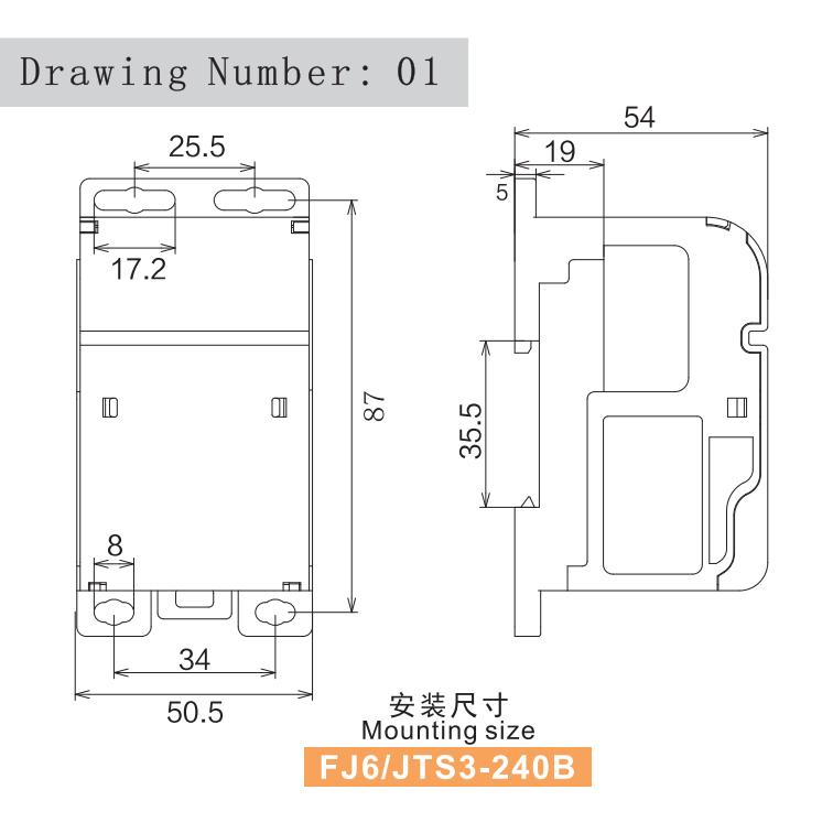
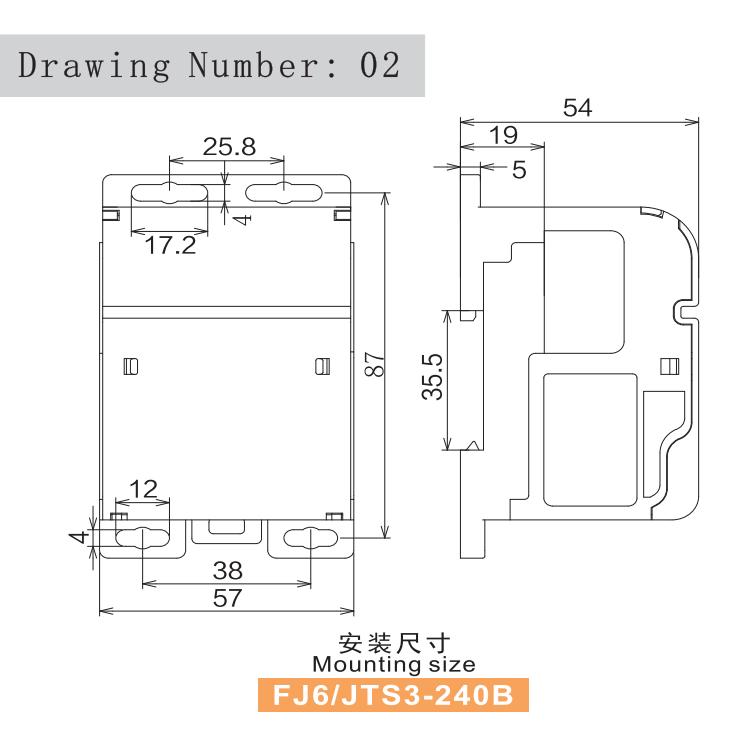
- Fixed mounting on base plate using M5 screws.
- DIN rail mounting on standard 35 mm rail (TH-35).
Installation Notes
- Installation and wiring shall be carried out with the power supply disconnected.
- During installation and operation, ensure conductors are fully inserted into the clamping area.
- When using cable lugs or copper busbars for line-in connection, ensure clean and flat contact surfaces.
- After installation, all connection points shall be checked for secure fixing.
Outline and Mounting Dimension
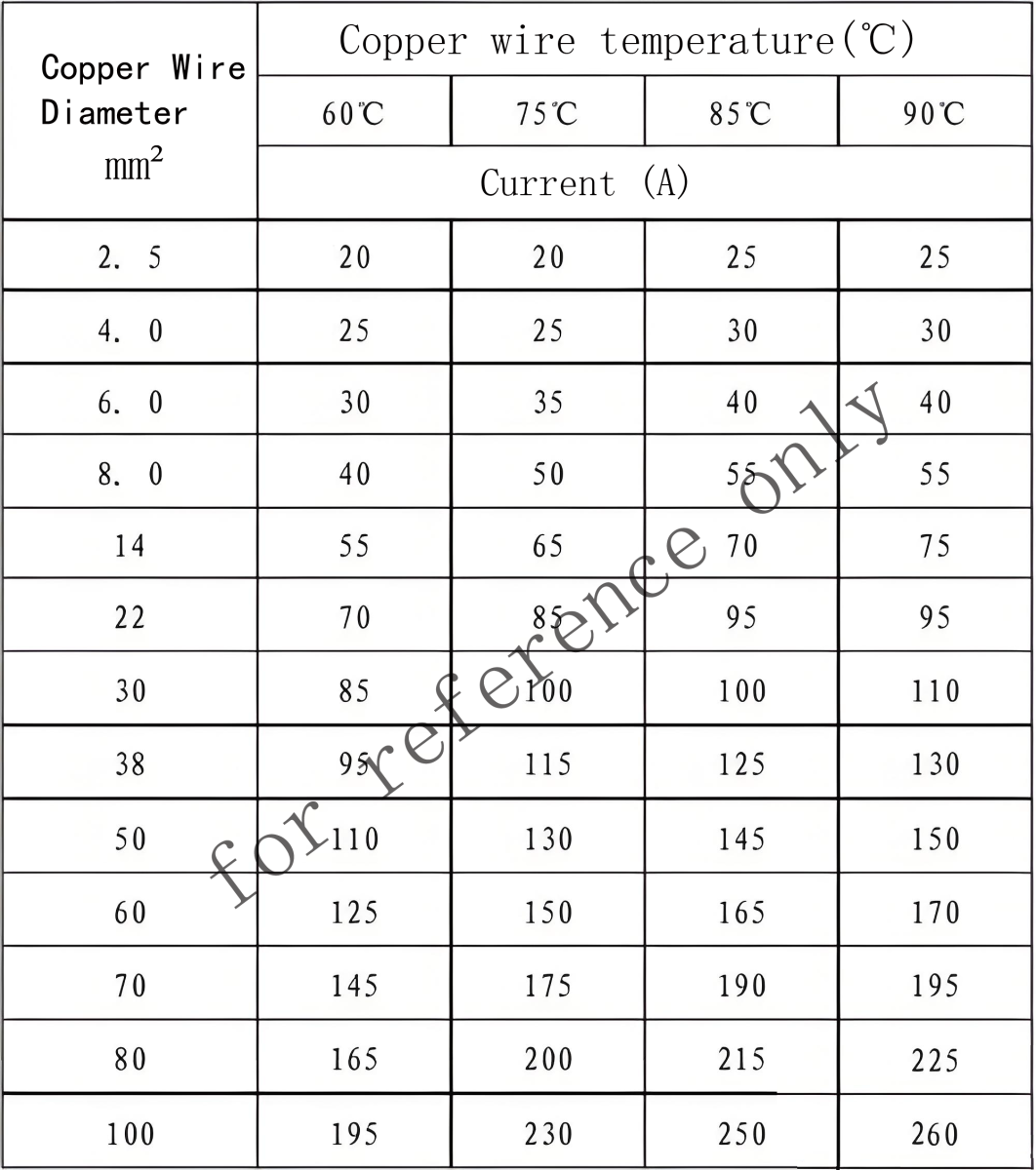
Reference Table for Copper Conductors for Incoming and Outgoing Line