


FJ6/UT Screw-type 1000V DIN Rail Terminal Block
Product Features
- Heavy-duty screw clamp connection for high current applications.
- Reinforced clamping frame and enlarged current bar design for increased current carrying capacity.
- Extended creepage and clearance distances for rated voltages up to 1000 V and above• Reliable electrical contact suitable for large solid and stranded conductors.
- Robust terminal block structure for long-term operation in demanding environments.
- Suitable for standard TH35 DIN rail mounting.
- Clear marking surface for easy circuit identification.
- Potential distribution via dedicated plug-in jumpers only, ensuring electrical safety in high-voltage applications.
- Compatible with complete UT series accessories.
Detailed introduction
Application
The UT series screw-type DIN rail terminal blocks are designed for high-current and high-voltage applications in low-voltage power distribution systems.
They are suitable for installations requiring increased creepage and clearance distances, such as main power distribution, heavy-duty control circuits, and energy-related applications, providing reliable and secure connections for solid and stranded conductors.
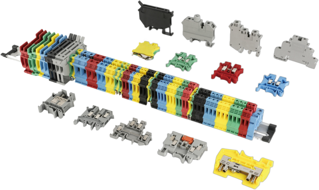
Key Specifications
| ||||||||||||||||||||||||||||||||||||||||||||||||||||||||||||||||||||||||||||||||||||||||||||||||||||||||||||||||||||||||||||||||||||||||||||||||||||||||||||||||||||||||||||||||||||||||||||||||||||||||||||||||||||||||
Installation and Operation
- Mount the terminal block onto the standard TH35 DIN rail.
- Insert the conductor fully into the clamping point.
- Tighten the screw according to the recommended torque.
- Use dedicated plug-in jumpers for potential distribution where required• Ensure all conductors are securely clamped before energizing.
Installation Notes
- Ensure conductors comply with the specified conductor ranges.
- Use dedicated jumpers only for potential distribution.
- Tighten screws according to the recommended torque values.
- Installation and maintenance must be carried out with power disconnected.


